


Project Overview
SolidWorks
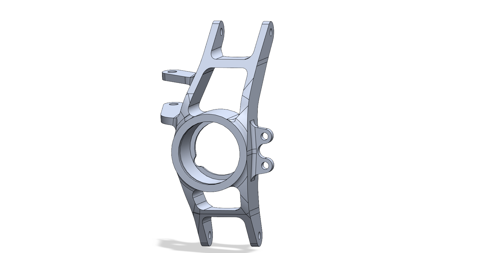
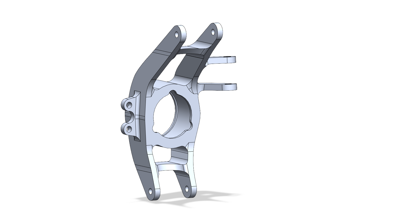
Attached are final SolidWorks screen captures of the final design. The custom Upright underwent a complete redesign.
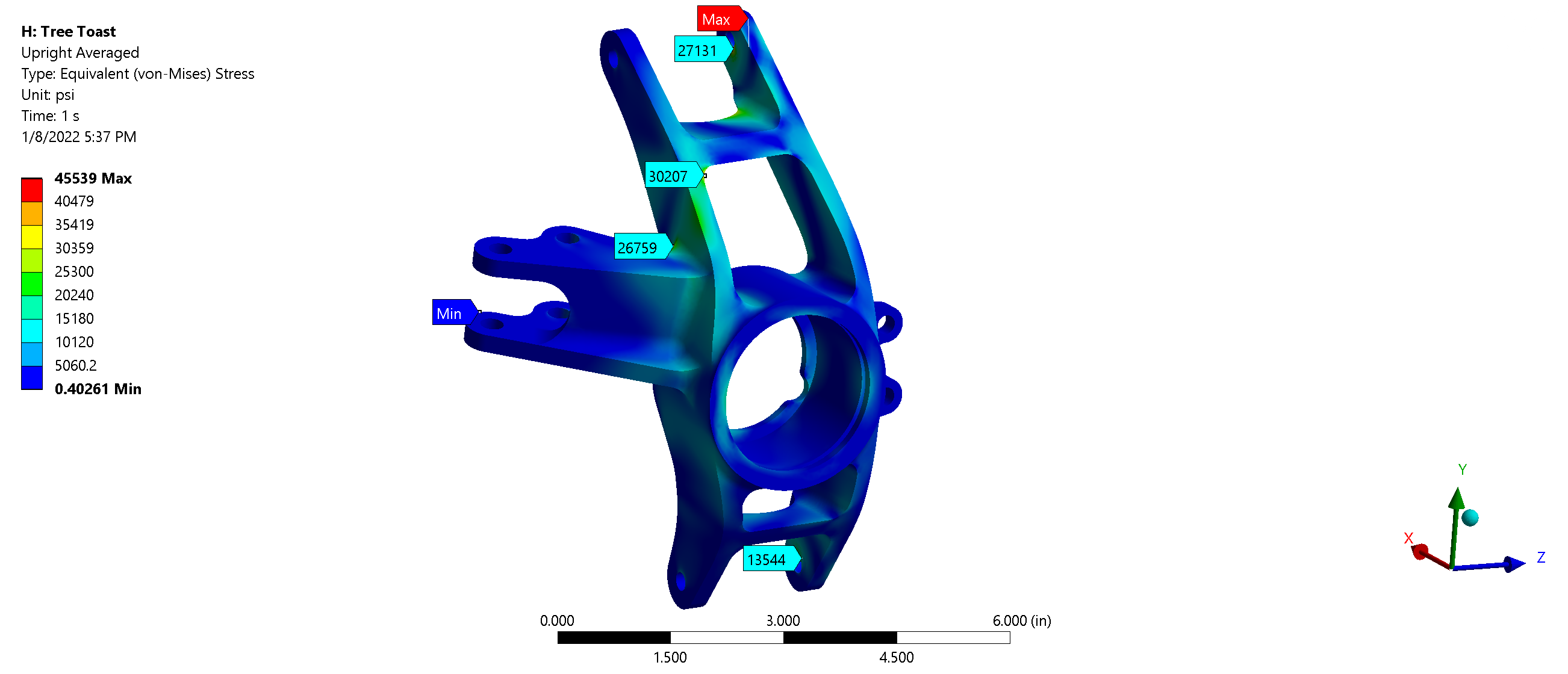
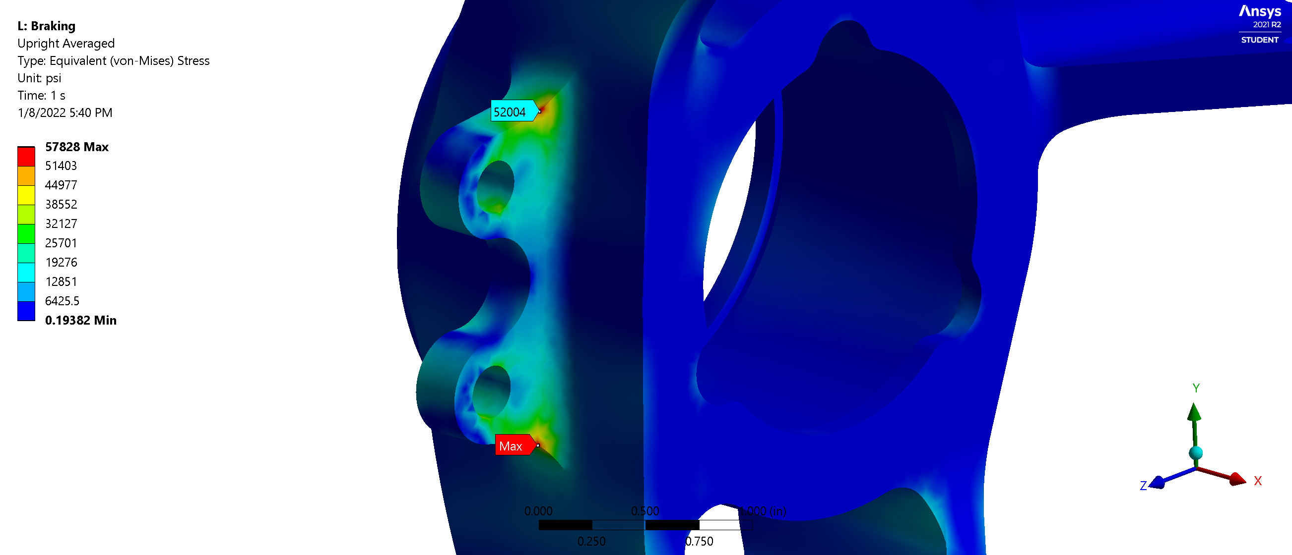
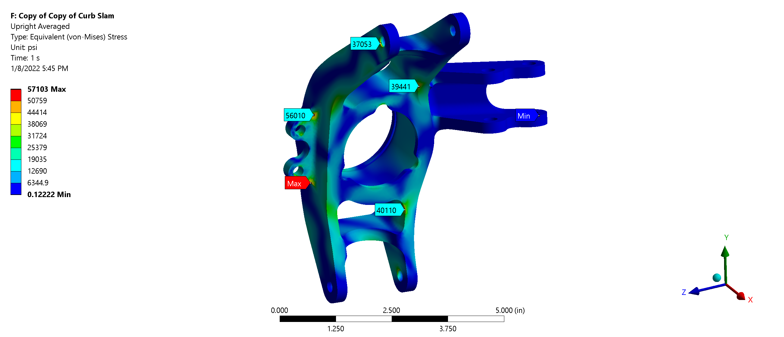
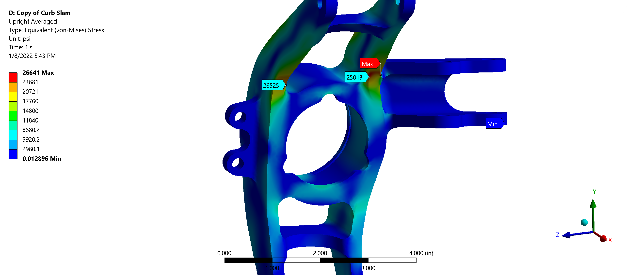
Finite Element Analysis
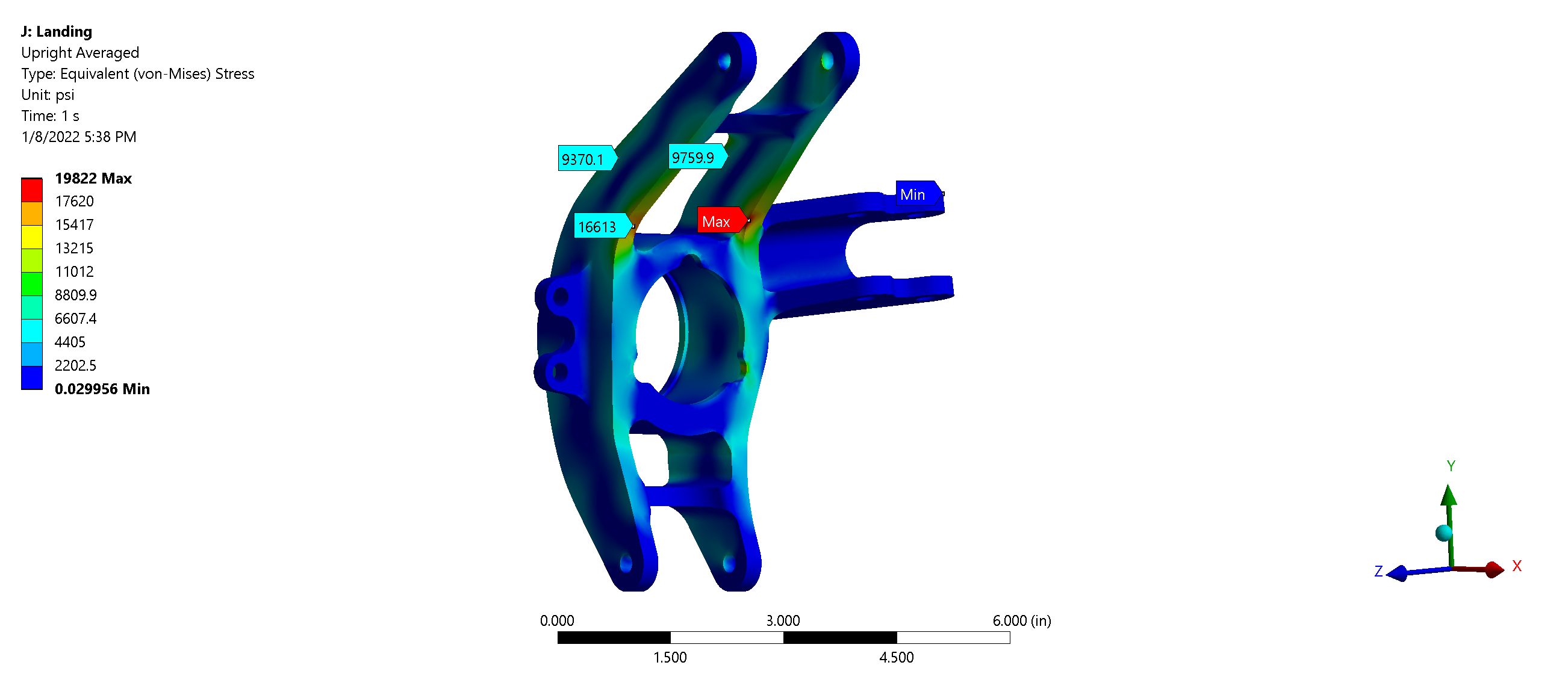
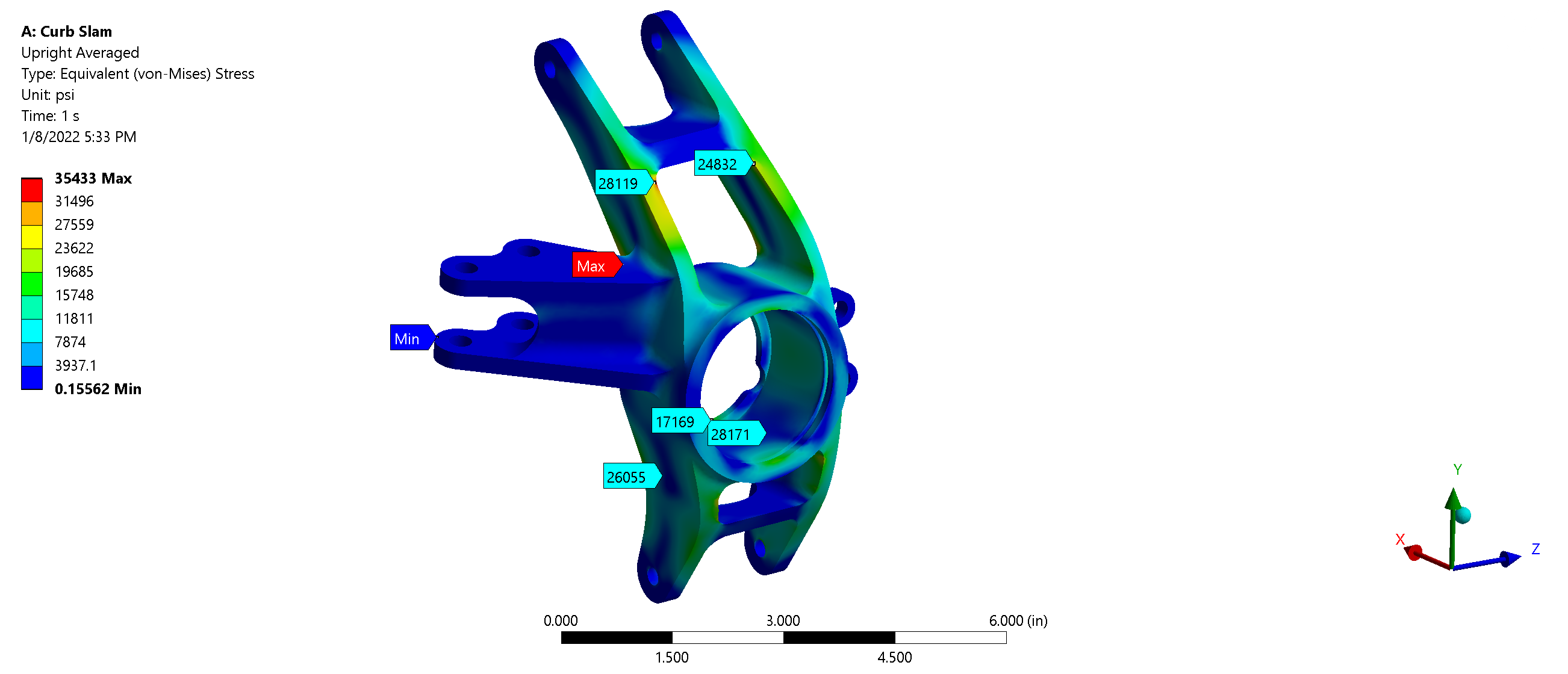
The Upright model was analyzed under different scenarios in a collision - Curb Slam, Tree Toast, Landing, and Braking. Additionally, these scenarios were combined to analyze the car in a more realistic situation.
Assemblies
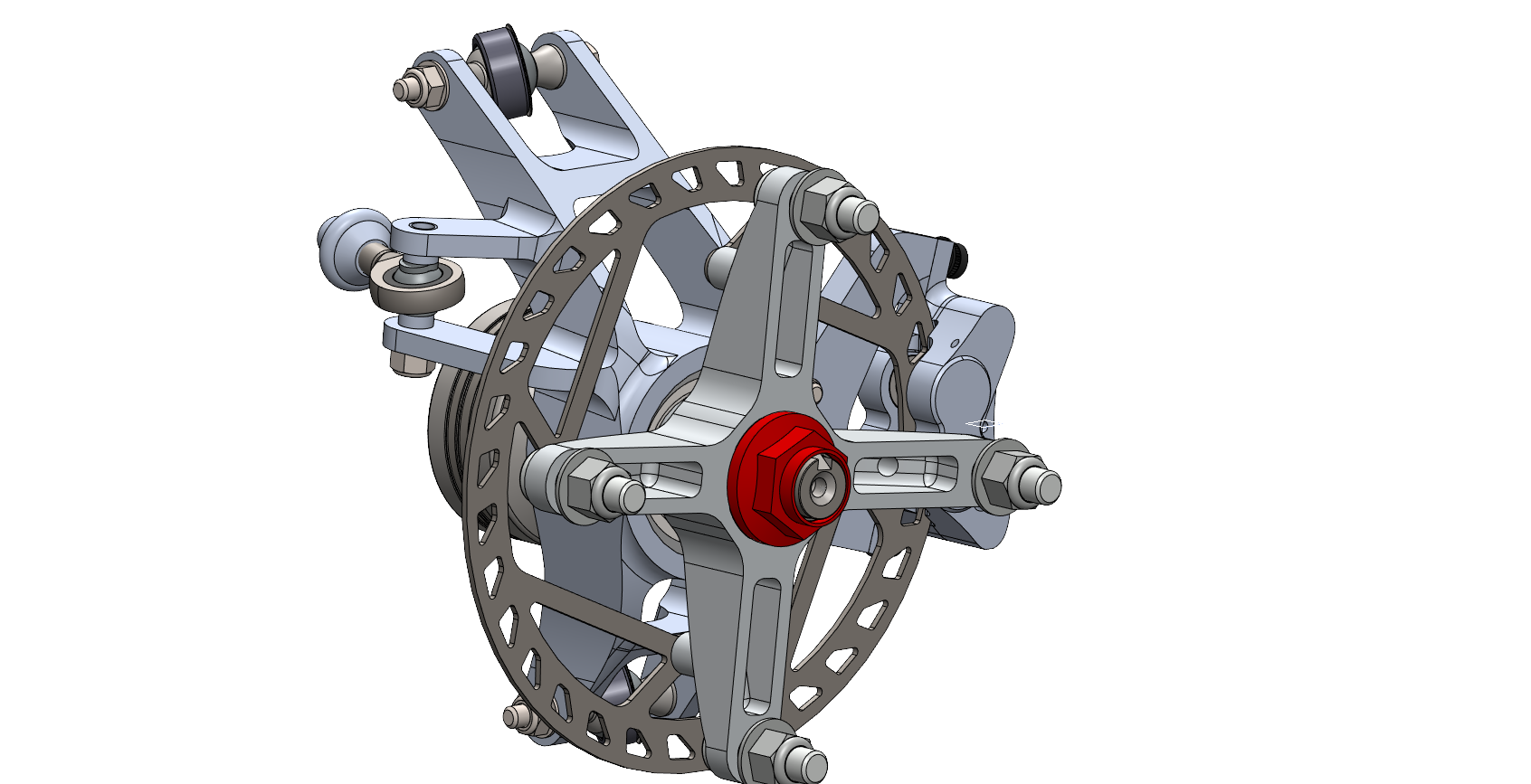
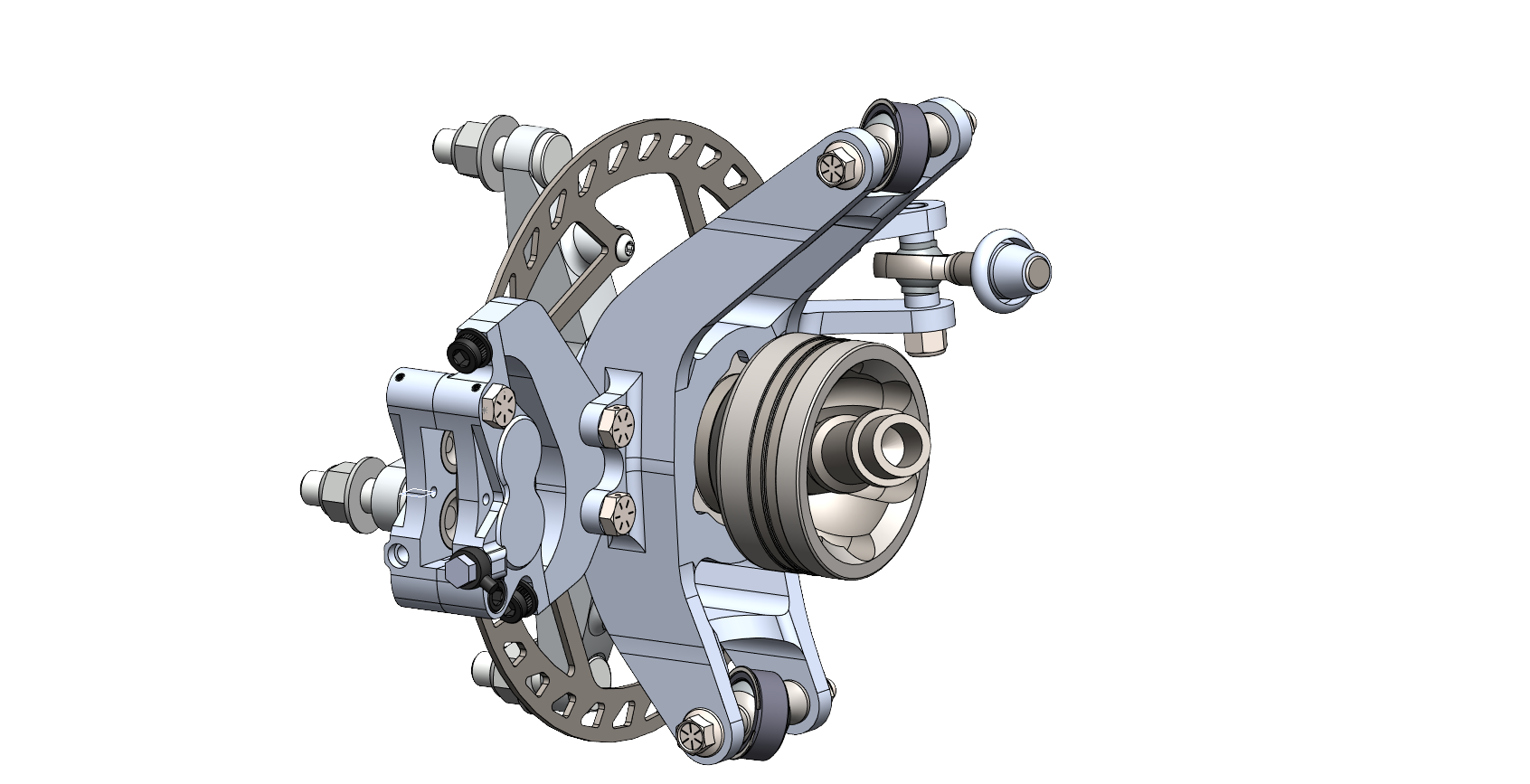
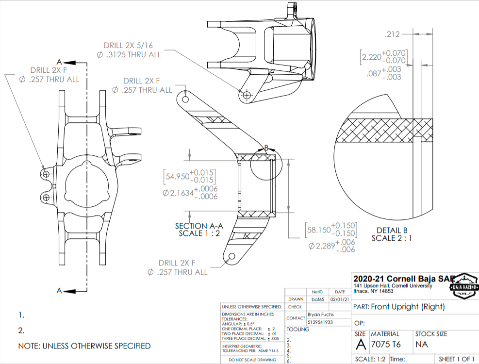
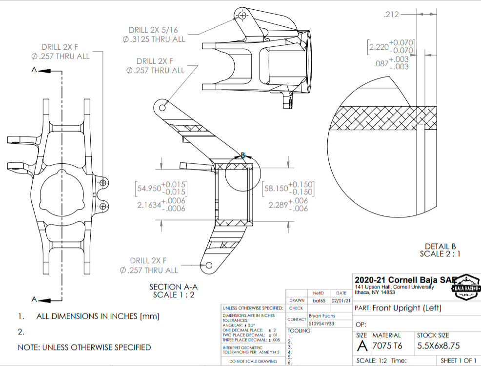
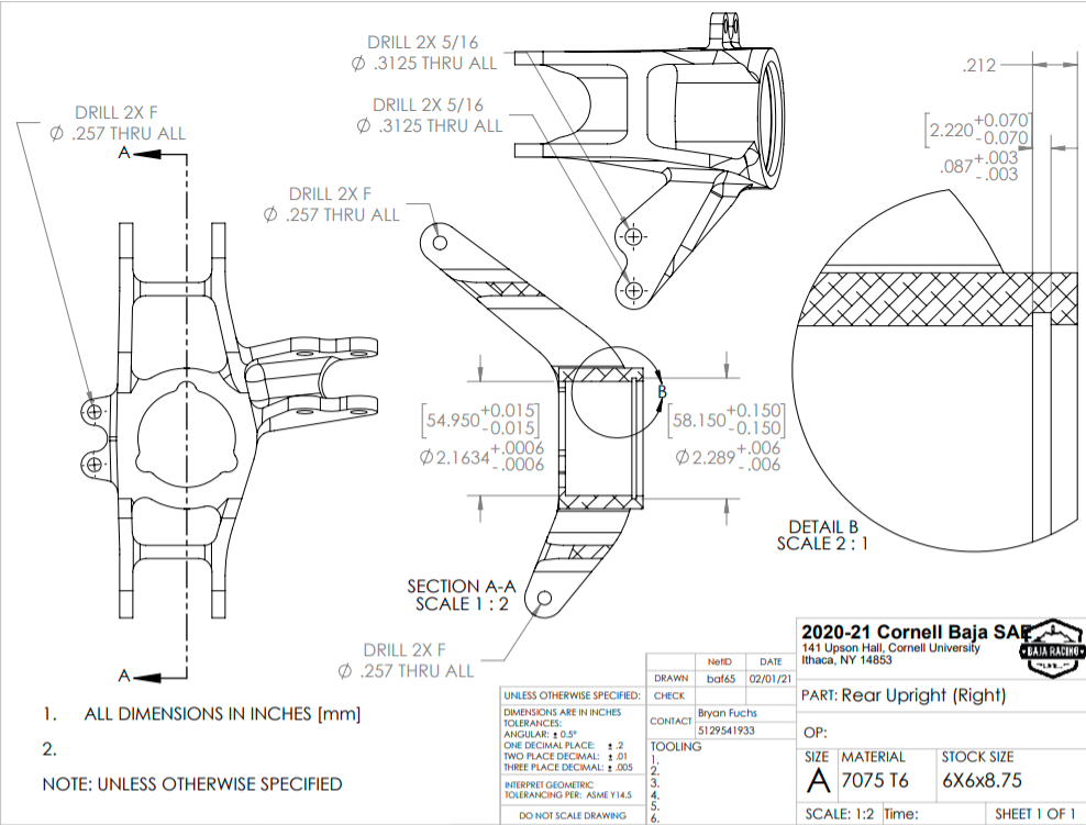
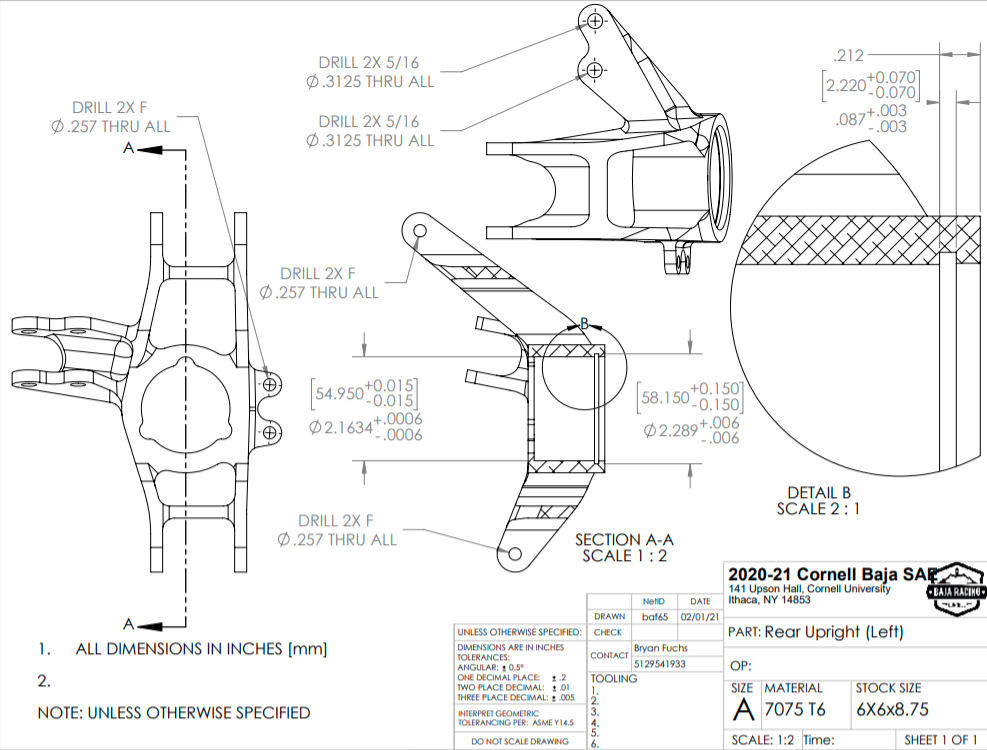
CAD Drawings
To ensure the proper tolerances were met during manufacturing, CAD Drawings had to be made for the machinist.
Tools Used
SolidWorks
ANSYS Workbench
Final Product
The Upright was successfully manufactured and competed in the '20-'21 Baja Competition Season.