


Project Overview
My redesign of the calipers were a custom fixed caliper that utilized identical pistons in each caliper. This meant that there would only need to be one version of the caliper manufactured for all applications on the car. Last year, we had 3 unique calipers on the car. With my design, the car would be equipped with 1 unique caliper which significantly reduces manufacturing, servicing, and design time. This was a huge improvement to the previous system. Additionally, the caliper was designed after all purchaseable components were sourced which meant that there were constraints that had to be designed around. This proved to be challenging because of packaging concerns in the corners as well as the rear gearbox. Nonetheless, I worked hard alongside my fellow teammates and accomplished inboard braking as well as similar calipers to be used on both left and right corners.
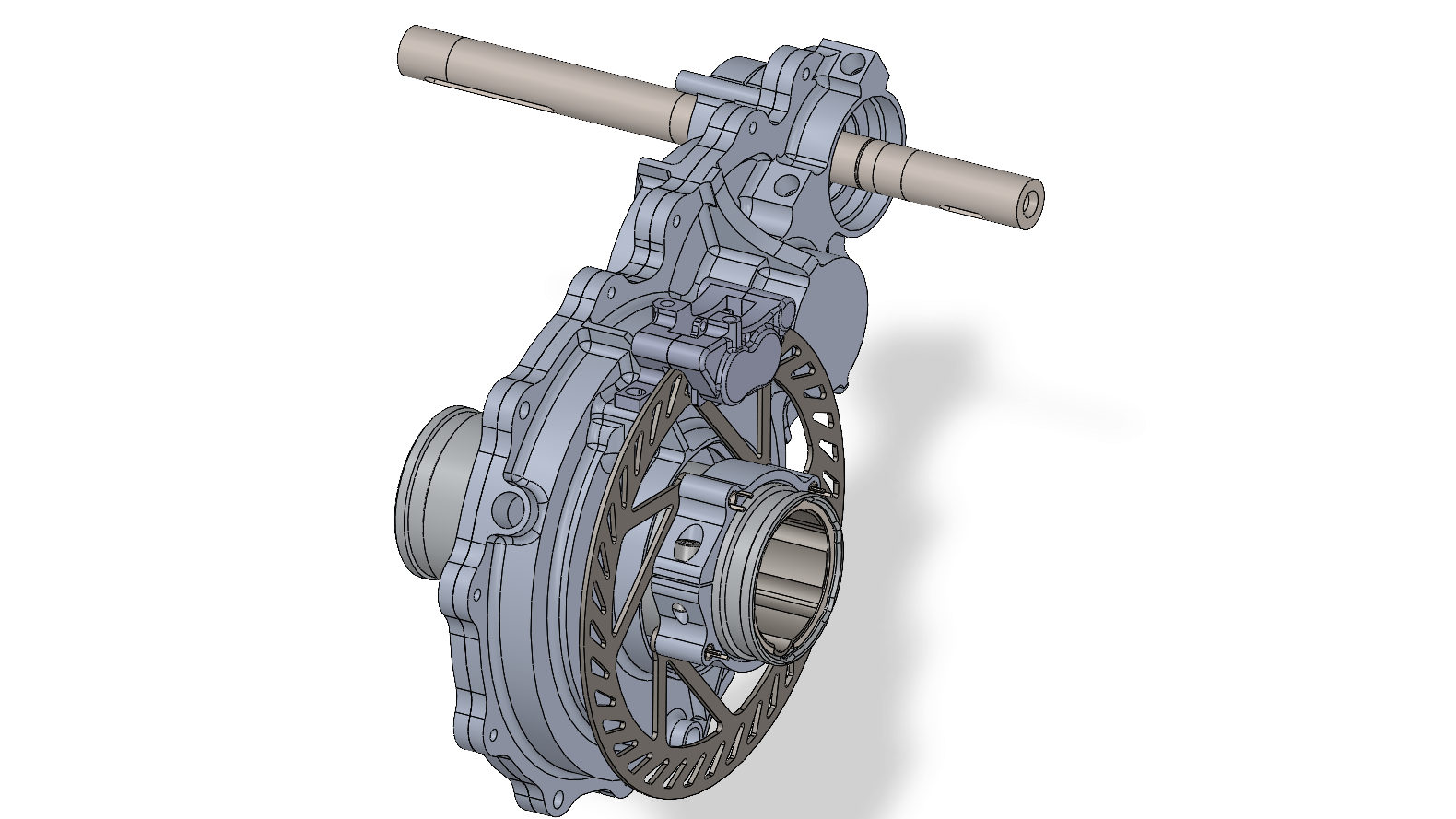
SolidWorks
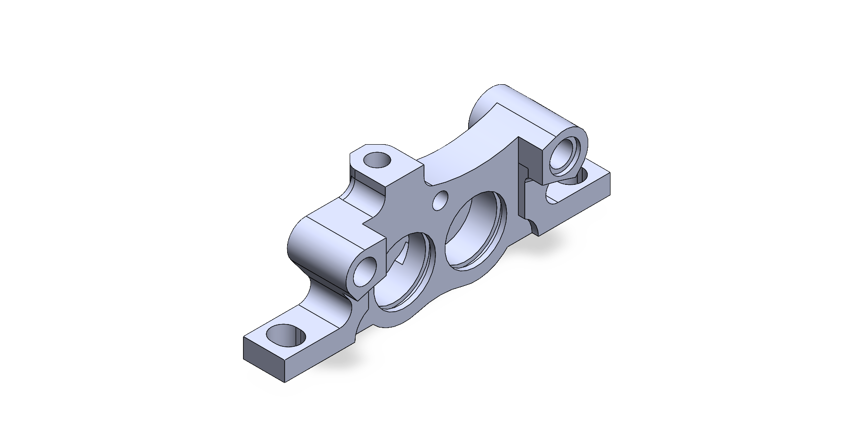
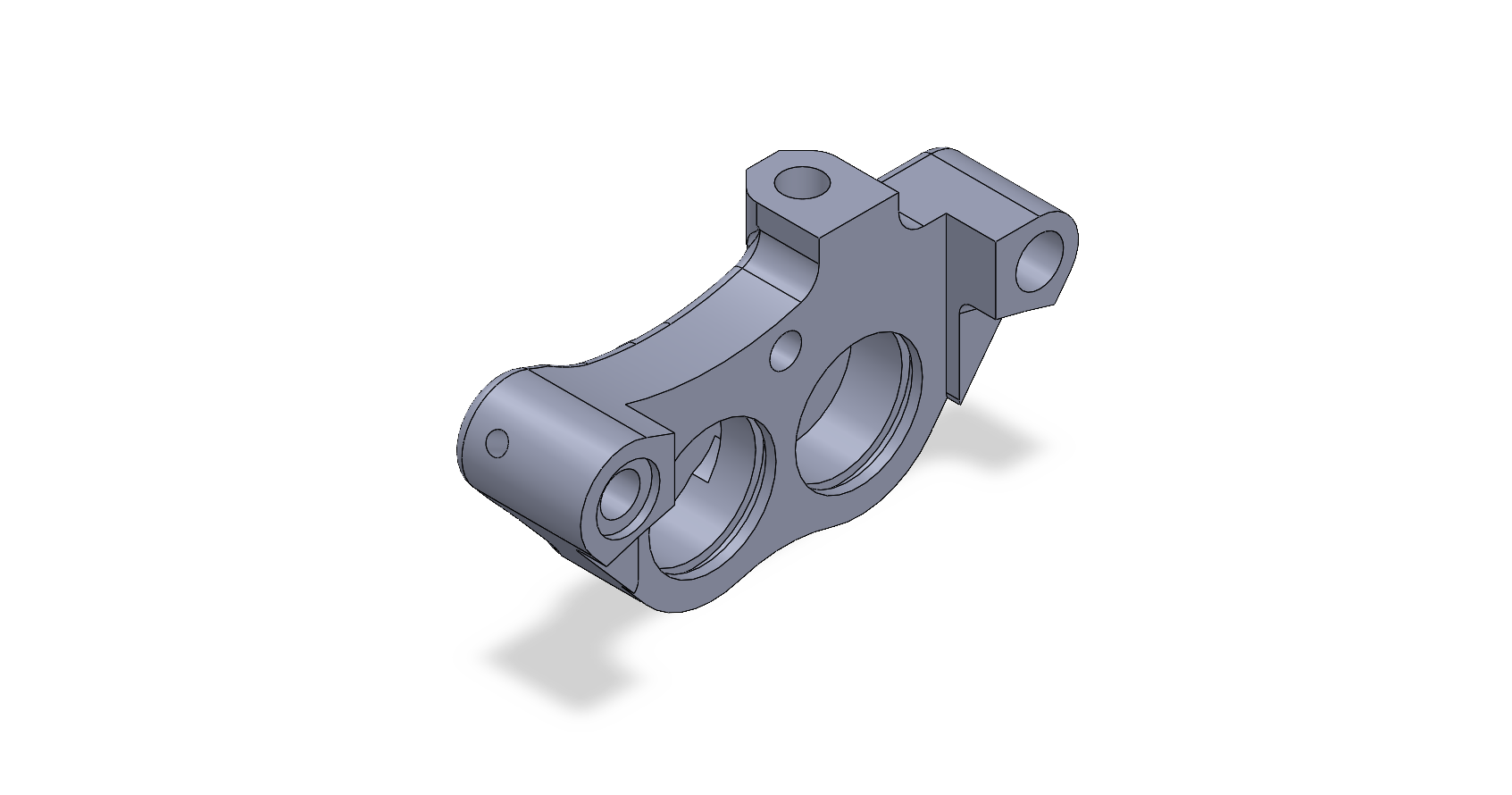
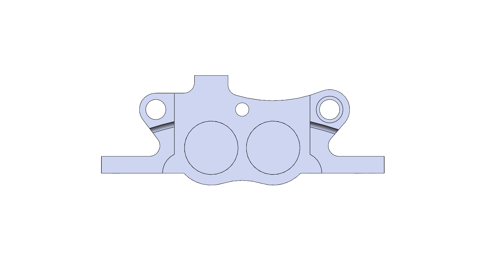
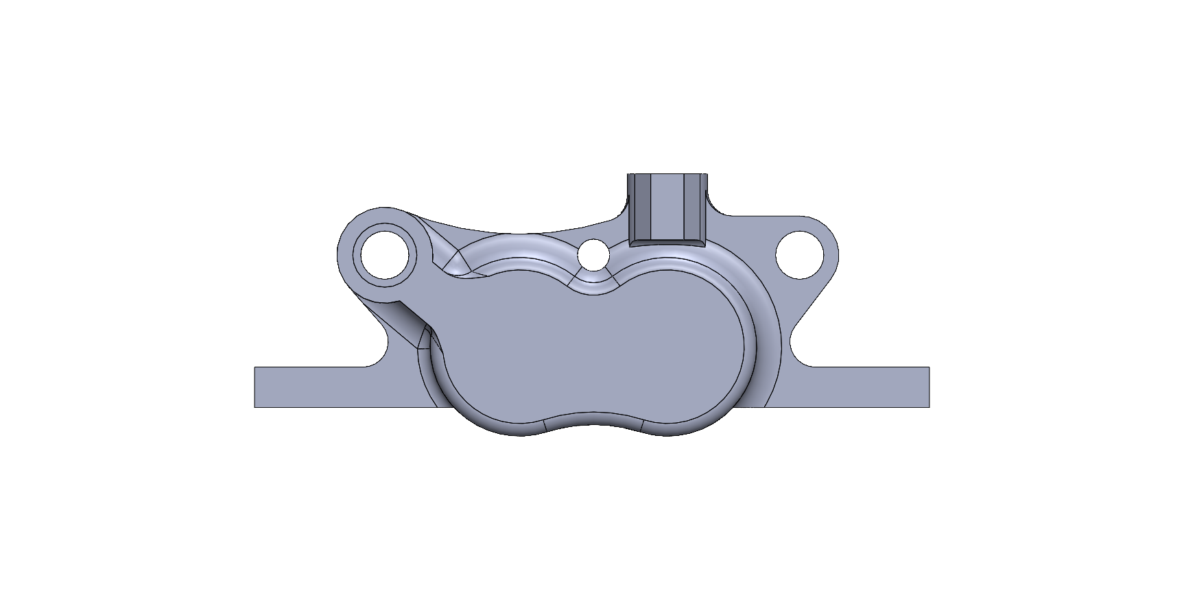
Attached are final SolidWorks screen captures of the final design. The custom fixed caliper was CADed from scratch and inspired by previous year's caliper models.
.PNG)
.PNG)
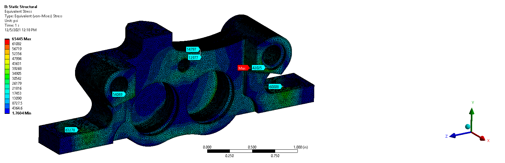
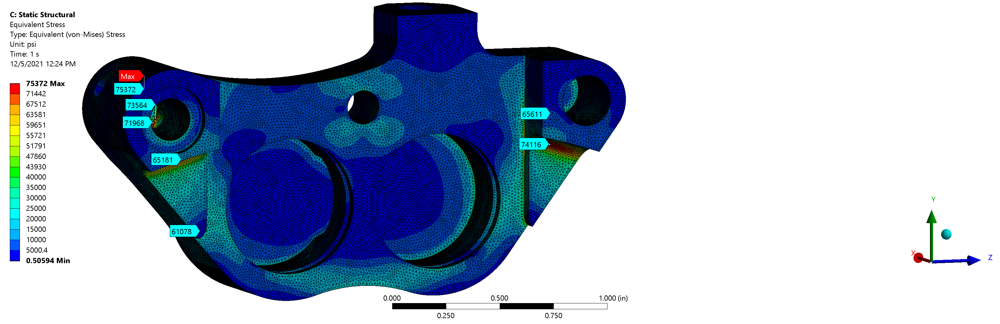
Finite Element Analysis
The Caliper model was analyzed on ANSYS Workbench under max pressure loads attained by the strongest team member panic braking. This produced a 250lb pedal force and after some simple calculations with pedal advantage as well as bias bar, the max pressure observed by the system was obtained - 2450psi.
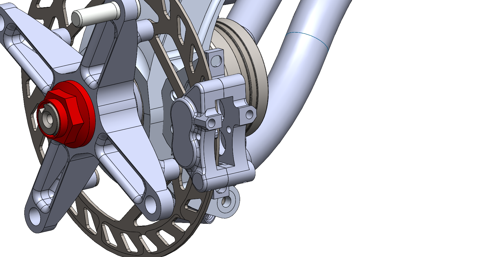
Assemblies
The most challenging part of the process was ensuring that the clearance betweeen the Caliper and all integrating parts were within tolerance. For this season's design, the limiting factor was between the caliper and the hub arm extensions for the rotor mounting bolts. With the deflection the hubs saw due to a crash analysis, the deformation was greater than the clearance between the two components. With that, I had to change the design of my caliper to ensure the necessary clearance was obtained.
Tools Used
Pending...
Currently the Caliper is in the process of being manufactured and assembled, I will update this page with the manufactured custom brake caliper upon completion.
Current Progress